Projects as a Product Engineer at Sparkmate Paris
Quick Description
I did a 4-month co-op at the Sparkmate Paris office from May - September of 2024. Sparkmate is an engineering consulting company that builds unique, innovative mechanical and electrical projects.
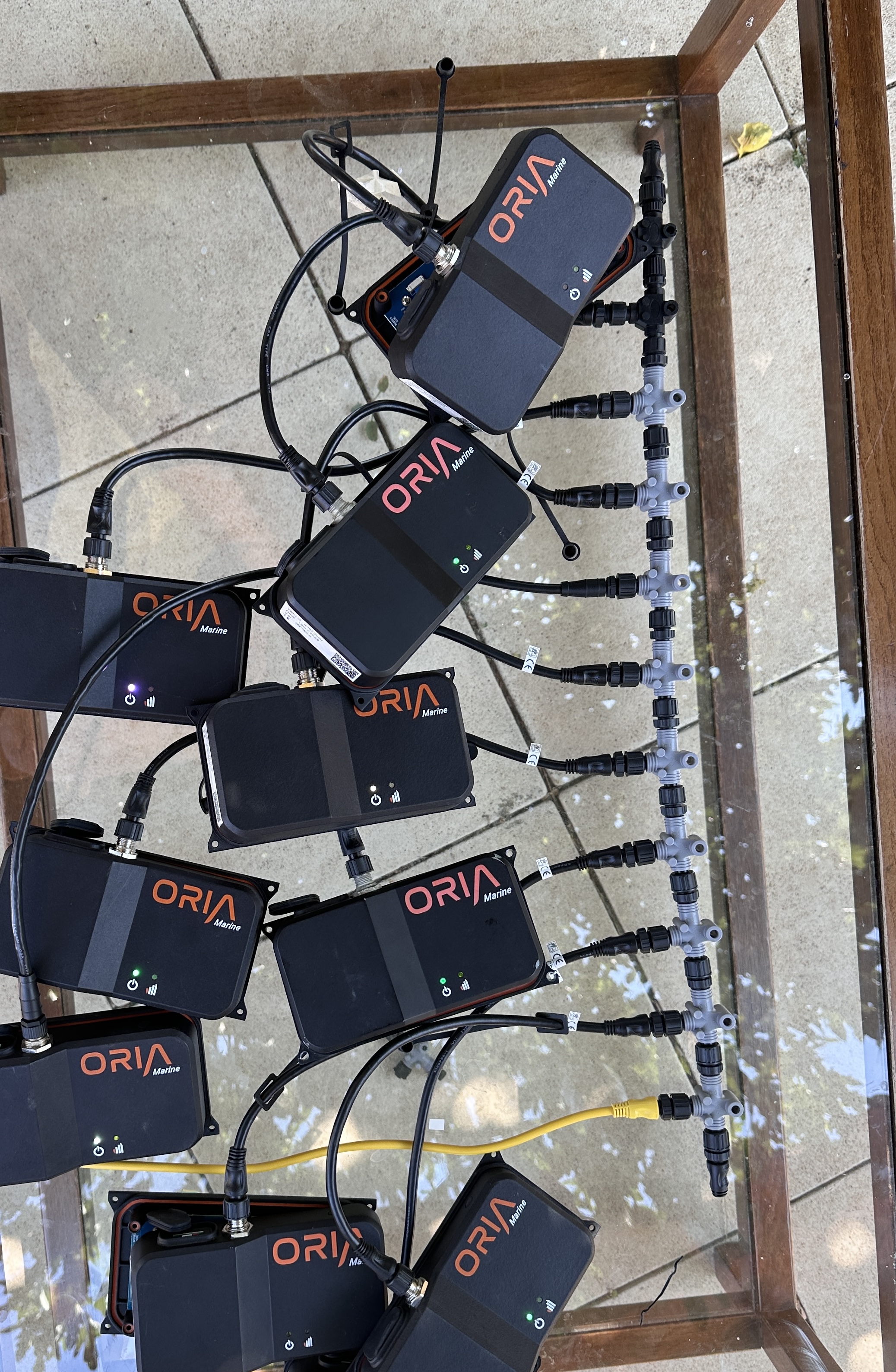
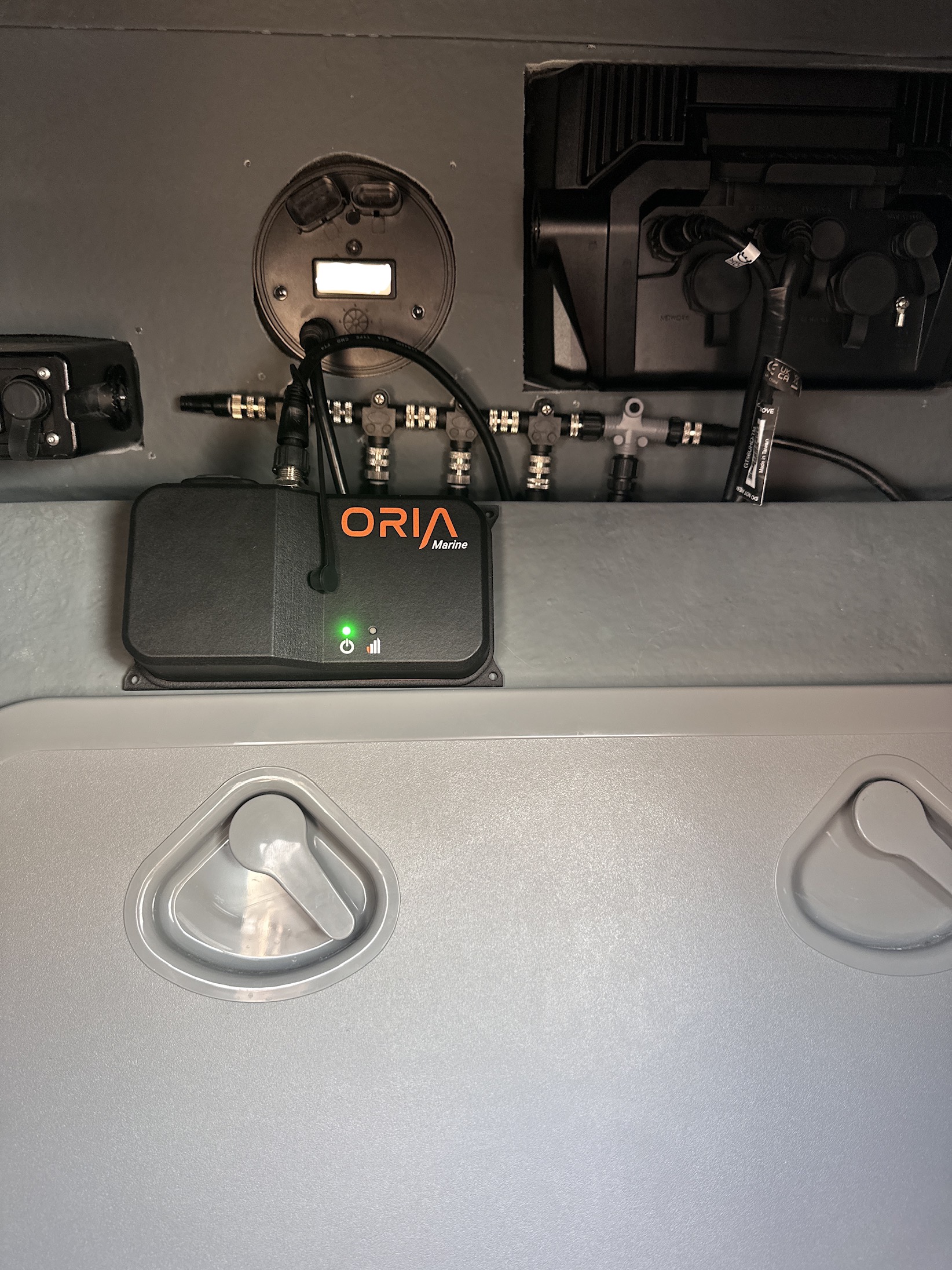
Oria Marine VDR
Oria Marine and Sparkmate collaborated to make a box that monitored boat fuel-efficiency, and displayed other statistics. These boxes were used during the Paris 2024 Olympics at the sailing competition in Marseilles, France! To read more about Oria Marine, visit their home page here: Oria Marine.
For this product, I worked on two projects. One was developing a prototype firmware that would track the force and frequency of the impacts that the boat would experiene while on the water. The second project was working on the main, existing firmware of Oria Marine and fixing several large issues that prevented the code from running. The firmware was written in C++ and utilized RTOS, both of which I was not familiar with prior to the project. Debugging RTOS firmware is much more difficult than debugging software because it is challenging to step through real-time dependent code. And becuase the product was on a PCB and utilized almost all of the microcontroller pins, JTAG debuggers were not an option.
Working on existing firmware is challenging in its own way, because it is code that somebody else had written. The previous engineer that had created this code was no longer at the company, so I had limited help in understanding the software. However, I succesfully familiarized myself with the firmware by carefully reading through the documentation, making flow charts of the firmware, and tinkering with the functions to fully understand the functionality before attempting to fix the major existing bugs. I then used creative techniques to narrow down where the issues were in the firmware, and single-handedly developed fixes for the issues. I worked over 80 hours in one week in order to have the product ready for testing and deployment so that it would be ready in time.
I also helped debug and fix the physical boxes themselves. Types of issues included, poor sim card reading, broken batteries, overheating components, and etc.
Part of testing and debugging this product involved going to the Olympic sailing site and mounting the boxes in the boats, then running the boats to see if the box behaved as predicted. Below are some photos of me during those visits!

Murfy Motherboard
Murfy and Sparkmate collaborated to create a service that will refurbish broken washing machines in order to combat waste in France. It is an excellent environmentally-friendly business, and you can read more about them here: Murfy.
For this project, I helped create version 4 of the motherboard for the washine machines. This involved understanding the design decisions behind the previous versions, discussing additional technological needs for the new revision, and identifying areas of improvement. I created comparison tables to choose any major new equipment like microcontrollers and digital ICs for the new PCB. I designed the new schematic, specced materials, and performed revisions based on mentor feedback to perfect the circuit. I also performed work on the physical layout of the PCB, however my internship ended before I could finalize the layout.
Designing this PCB helped me familiarize myself with practical applications of many electrical engineering theories that we have learned but didn’t apply - for example, filters and transistors- and also was a great learning opportunity on developing circuits for microcontroller chips, as opposed to buying already prepared dev boards. In addition, I learned a lot from my mentor on how to consider not just the circuit itself, but the purchasing and manufacturing requirements to produce the board - focusing on standard component packages, minimizing discrete components, and best practices for reliable circuits. This is great knowledge to have before entering the industry as it can help reduce cost and wait times on PCBs.
To design this PCB, I used KiCAD. Due to privacy reasons, I cannot post photos of the schematics or my work, but you can see me in the picture below standing next to the ad for the company in the Parisi metro!

Other Hardware Debugging Projects
There were other projects that I did during my internship that were focused on hardware debugging. These were great experiences because in university, the typical hardware debugging experience that we get as students is only on your own, PERSONAL circuit: In these cases, you know your own schematic, what components do what, and it is easier to review and identify the issue. In industry, it’s likely that one will have to debug a circuit they did not create. This summer was the perfect opportunity for me to be exposed to this scenario.
I reviewed complex schematics that were not my own, learned to identify functional blocks within schematics, and developed safe practices on how to test hardware in controlled environments.
One tricky scenario I ran into was that the box was buggy while operating on it’s own, but somehow functioned normally everytime I would probe it with an oscillscope. Using my knowledge from past engineering projects, I was able to quickly identify that the issue was due to digital noise! And that the impedance of the oscilloscope was helping to quiet the communication line and allow for two components to communicate without issue. To warn others of this type of behaviour, and to prevent digital noise issues in the future, I wrote a small blog post for my fellow product engineers in the company on how to account for digital noise in your circuits in advance:
- All digital grounds should be connected together and to the microcontroller ground pin
- Do NOT connect to the ground of a separate battery or power supply. Connect only to the ground of your microcontroller
- Because ground is supposed to act like a “reference” to your signal’s highs/lows, you want devices that are communicating digitally with microcontroller to SHARE the ground with the microcontroller so that their reference is the same.
- Do NOT connect to the ground of a separate battery or power supply. Connect only to the ground of your microcontroller
- Things that help with digital noise
- If you have a PCB, a ground plane helps with noise
- If you have loose wires:
- Wrapping ground wires AROUND your communication wires helps
- Make wires as short as possible
- Use pull-down/pull-up resistors so that logic is never floating
- Make sure the wires are reliably connected. Do not use jumper wires because the connection isn’t solid.