Project: 2 DOF Robotic Laser Pointer for ELEC 391 Course
Quick Description
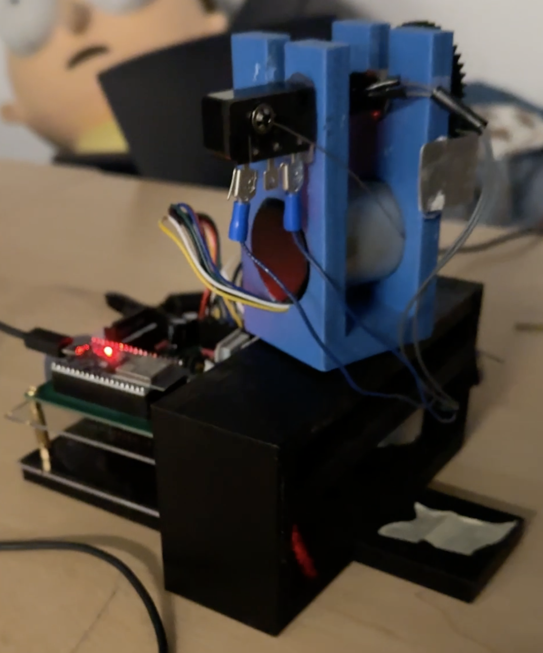
This was a project for our ELEC 391 course. The challenge was to build a robotic laser pointer with two degrees of freedom. The requirements were that we had to build everything from scratch, including the PID controllers for the motors. Meaning we could not use stepper motors! .
I was in charge of the controls and operational firmware for this project. I used techniques like Q-design and closed-loop testing to develop a robust controls sytem for the cheap DC motors that we were given. In addition, I developed efficient firmware while taking timing and complexity analysis into consideration. I also made the PID and path planning from scratch so that the code would run as quickly as possible and minimize the discrete time step in the controls system.
Process
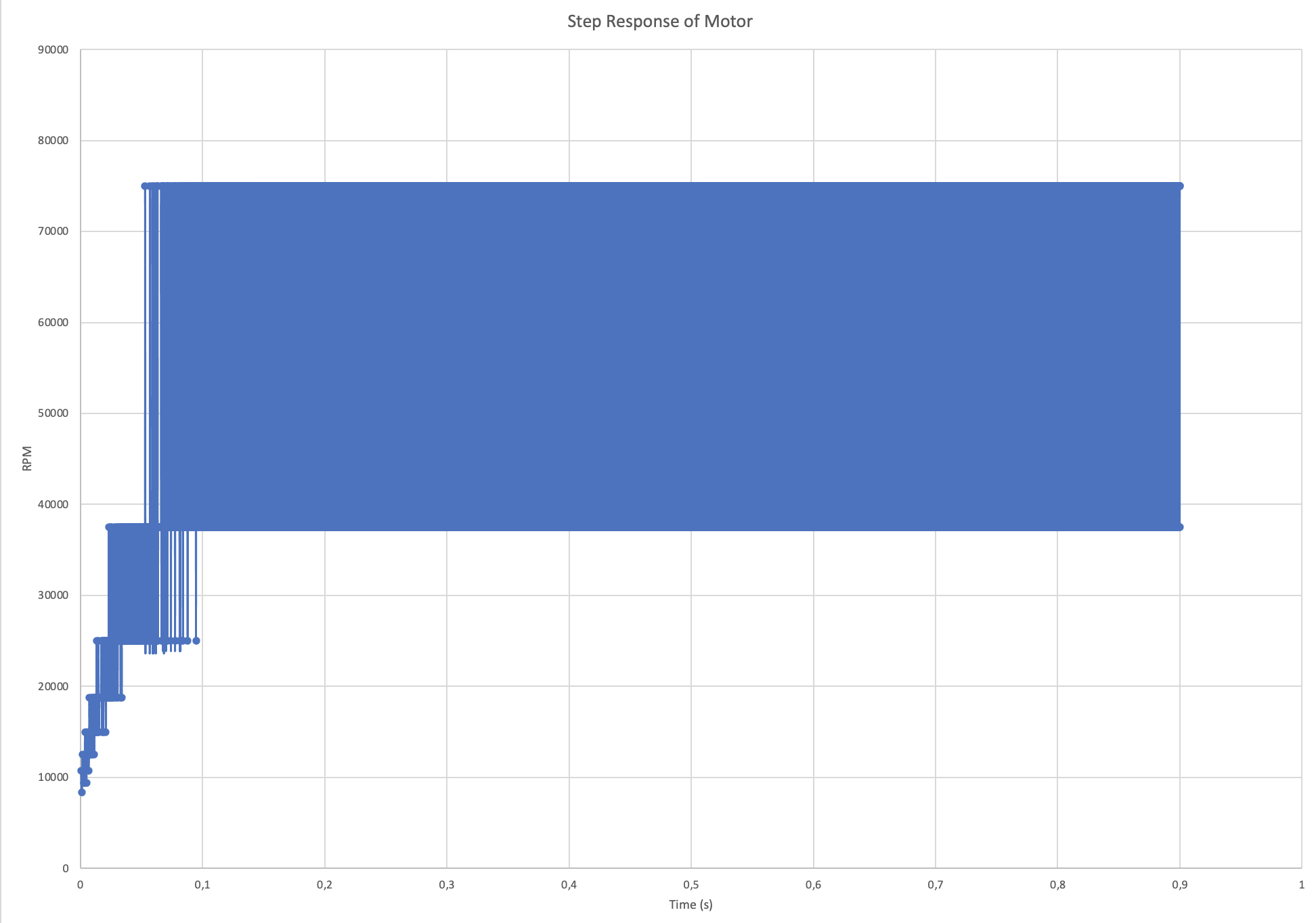
We initially tried to develop a system model for our DC motors by tracking and plotting the change in rpm while it reached full speed when a full 12V was applied to the terminals. However, because of the speed of the motors reaction and the limited sensing capabilities of the encoder that we initially used, we had spaced apart discrete data, and we had to also take the derivative of the collected data. All of that meant that the step response was very noisy and had a lot of discontinuities. The below graph was from one of the experiments:
Eventually, my teammates succesfully developed a very accurate and reliable encoder. I decided to use this encoder and designed a simple closed-loop proportional controller system for the motor. I tracked the closed-loop response to an input via the position of the motor. Which produced a much cleaner plot:
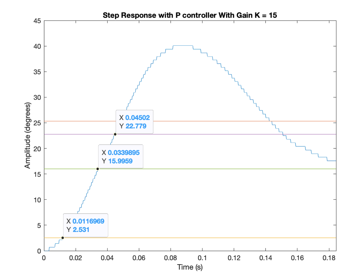
Instead of taking the derivative of the position to get RPM like the first time, I instead made a second order approximation for this plot, then worked backwards to figure out the system model from the negative-feedback closed-loop model equation:
Closed Loop Equation = Forward_Path / (1 + Forward_Path * Backward_Path)
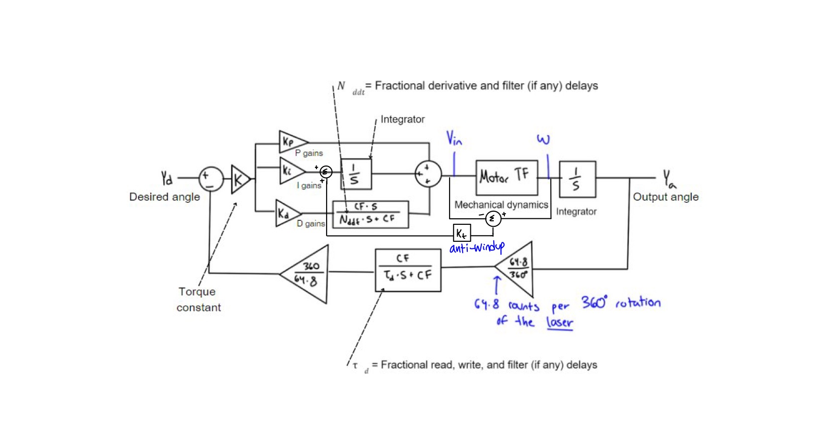
From there, I developed gains using multiple methods such as Q-design and as well as a newtonian search method for optimal zero placement based on ultimate gain optimization. Since the two motors had different loads - ie one motor was just spinning the little laser, and the bottom motor was carrying the entire weight of the top motor, it turned out that different PID design methods worked for the different methods. The general control loop, without the particular gains is as depicted below: