Project: Magnetic Field-Controlled Robot
Status: Completed Electrical Project for ELEC 291, a course at UBC. Role: Leader
Quick Description
The goal of this project was to design a magnetic field-controlled robot. It consists of two parts - are transmitter with two big inductors, and a receiver (the car). Our professor provided some schematics and code, but the challenge of this project was to integrate everything and complete the code.
The car had two modes:
- Controller Mode - receiving commands from the receiver to turn left/right, move backward/forwards, and turn backward left/backward right
- Tracking Mode - follow the receiver in any direction that it is moved, maintaining an exact distance of 50cm.
Materials Used
- PIC32MX130 microcontroller
- STM32L051 microcontroller
- MOSFET drivers
- M8275-ND Inductors
- many other tiny electrical components
Step By Step Playthrough
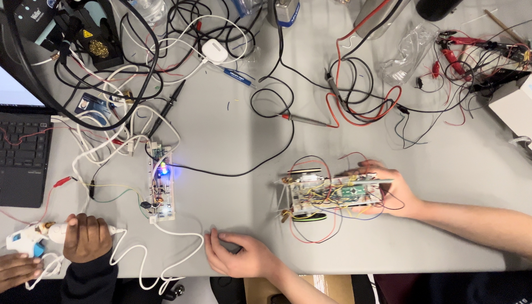
I was the leader of the 6 student team that worked on this project. I delegated tasks among the students (3 working on the transmitter and 3 (including me) working on the receiver (the car)) as well as significantly contributed to the technical design. Both microcontrollers were programmed in C.
My work on the transmitter included:
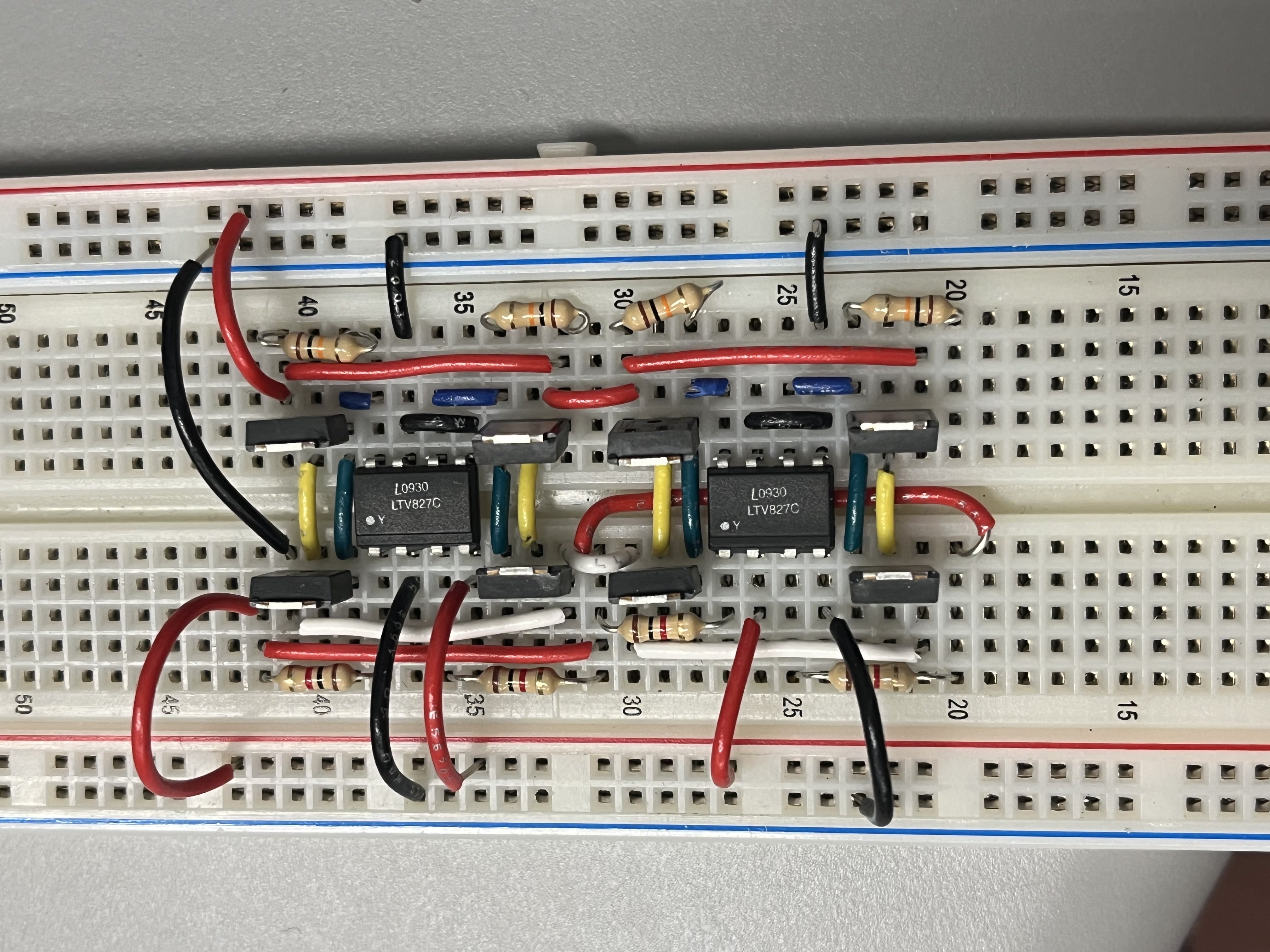
Constructing the H-bridge.
Because there is limited space on the car shell, we had to condense our circuit onto one breadboard - which meant the H-bridge had to be incredibly condensed. Here is a photo of the H-bridge I built:
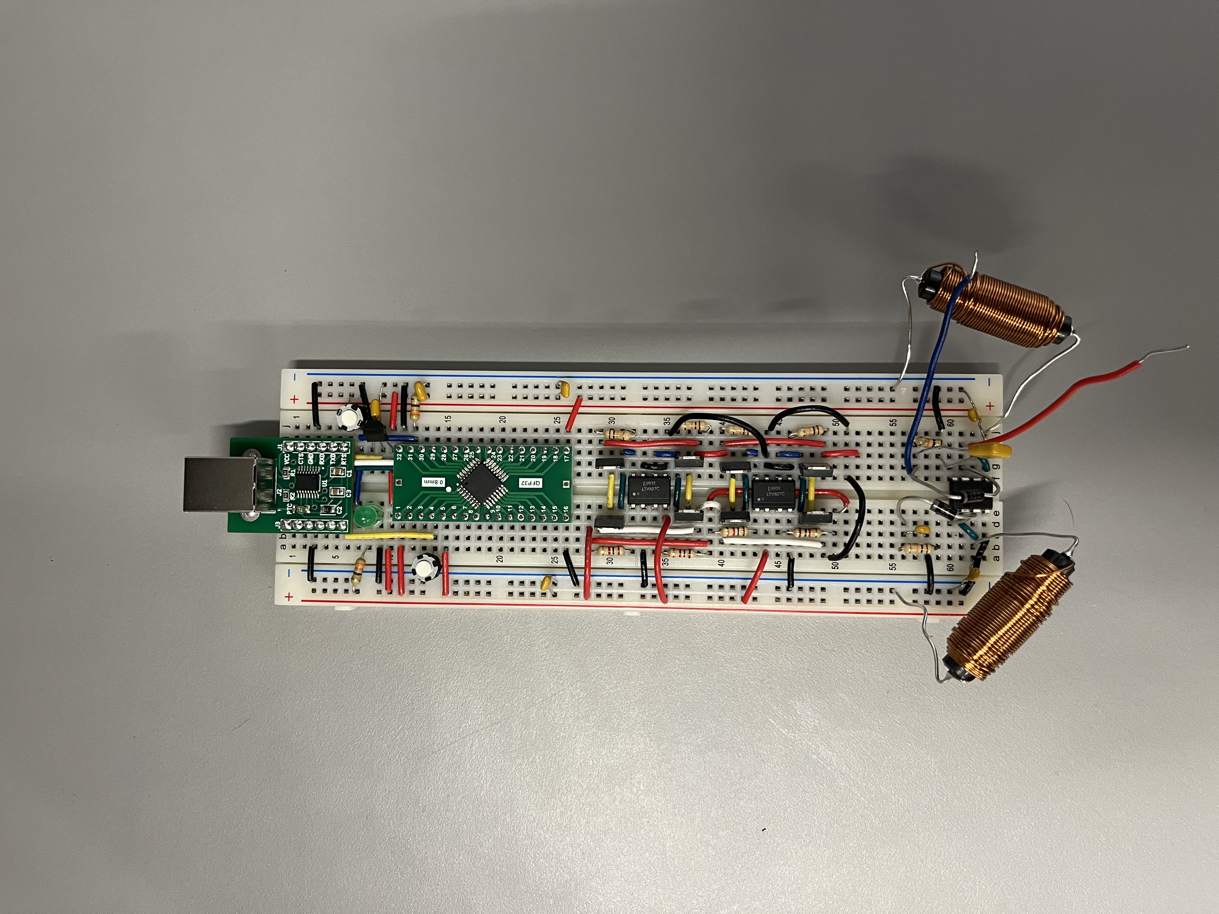
Integrating the Components
Then, we had to integrate the rest of the components: including the inductors that receive the signal from the transmitter, and the microcontroller that receives the signal, interprets it, and then controls the H-bridge. This is what it initially looked like:
Debugging
We tested each of the components individually before combining them (a lesson we learned from our past big project, where we did NOT do that…).
Unfortunately, the inductors were receiving a very weak signal. We tested the transmitter, and the measured voltage was exactly what it was supposed to be. This meant there was a problem with the inductors on the receiver, but we could not change them and had to think of other solutions.
Modifying the Design
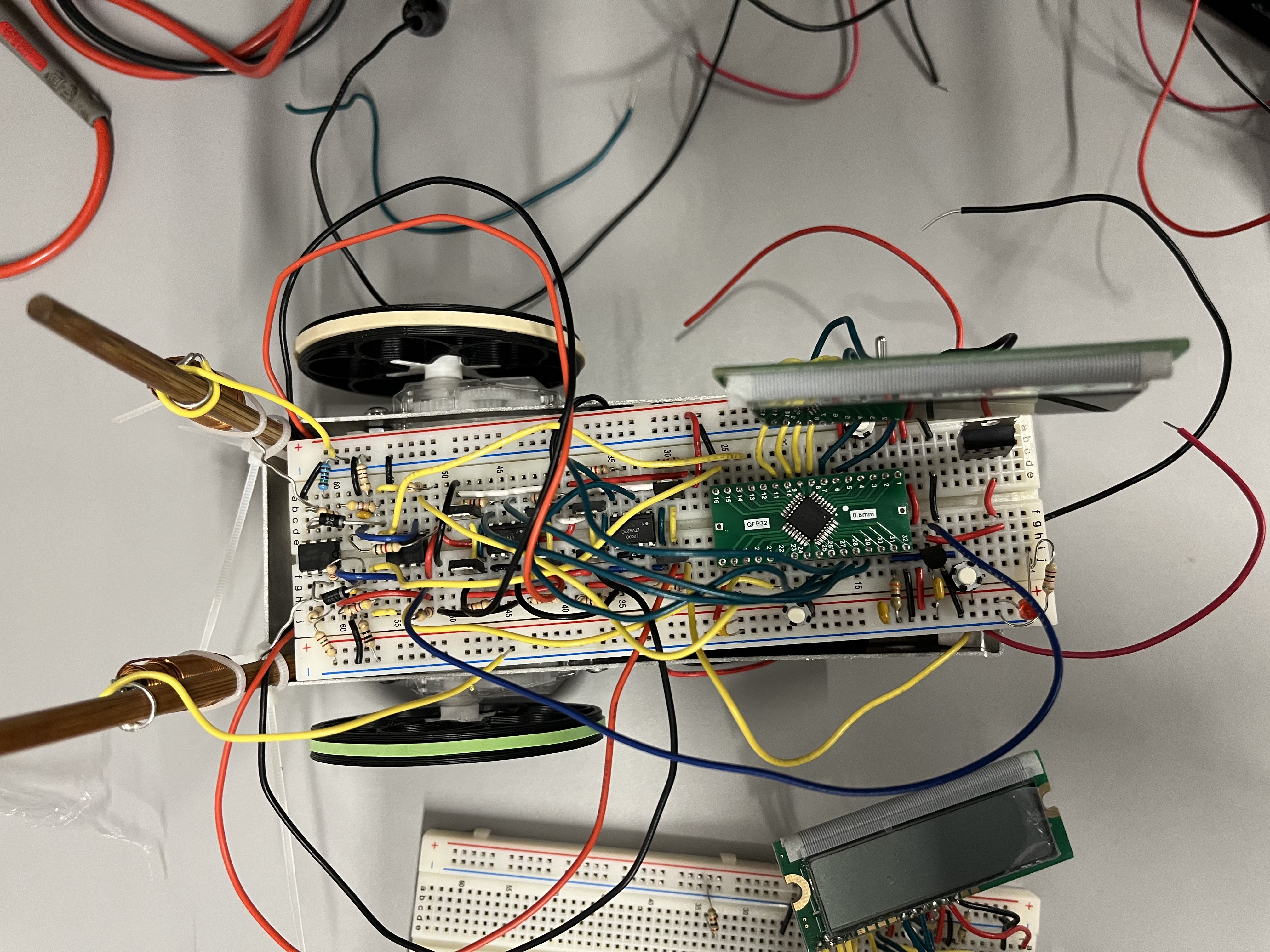
My solution was to add cascaded amplifiers on the receiver - this required a lot of trial and error to determine how much we needed to amplify the signal. This is the messy final version of the car (not pictured is the additional, tiny, chaotic solder breadboard we had stuffed underneath):
As part of the project, we were required to make a video (or write an essay) about this project. You can see my teammate’s (Ruth Tao) video on YouTube by clicking on the image below: