Project: Tracking Beacon
Status: Archived project for the UBC AeroDesign Team (Sensors and Controls Subteam)
Quick Description
I worked on designing a closed-loop control system with stepper motors and encoders to control the movement of a tracking beacon; this beacon was supposed to point an antenna at our plane while it is flying. This project involved creating a set of requirements to select the optimal motors and encoders for our design, purchasing the components, soldering them together, and (currently) writing code to create a functioning closed-loop system.
Materials Used
- Arduino Nano RP2040 connect
- Two stepper motors with built-in encoders Exact Model
- Two Motor Drivers Exact Model
- Salae Logic Pro Digital Logic Analyzer
- many other tiny electrical components
- Many, Many Websites
Helpful Links for Explorers
- Selecting a Motor Driver
- How to Control a DC Motor with an Encoder
- AccelStepper Library
- (pdf from Sparkfun) How to Use a Quadrature Encoder
Step By Step Playthrough
I was in charge of the electrical system for this project, and another mechanical engineering student on the same subteam was responsible for designing the physical beacon.
This will not be a detailed walkthrough, but here are the general steps I used:
- Research, research, and research. Understanding how encoders work, how stepper motors work, and how you can use one to control the other. All relevant links are included above.
- Picking a motor that is strong enough to push the beacon’s arm (according to calculations done by my fellow mechanical engineering student)
- Once the motor was picked, I chose motor drivers that were strong enough to power the motors that I had chosen and had the correct increment size.
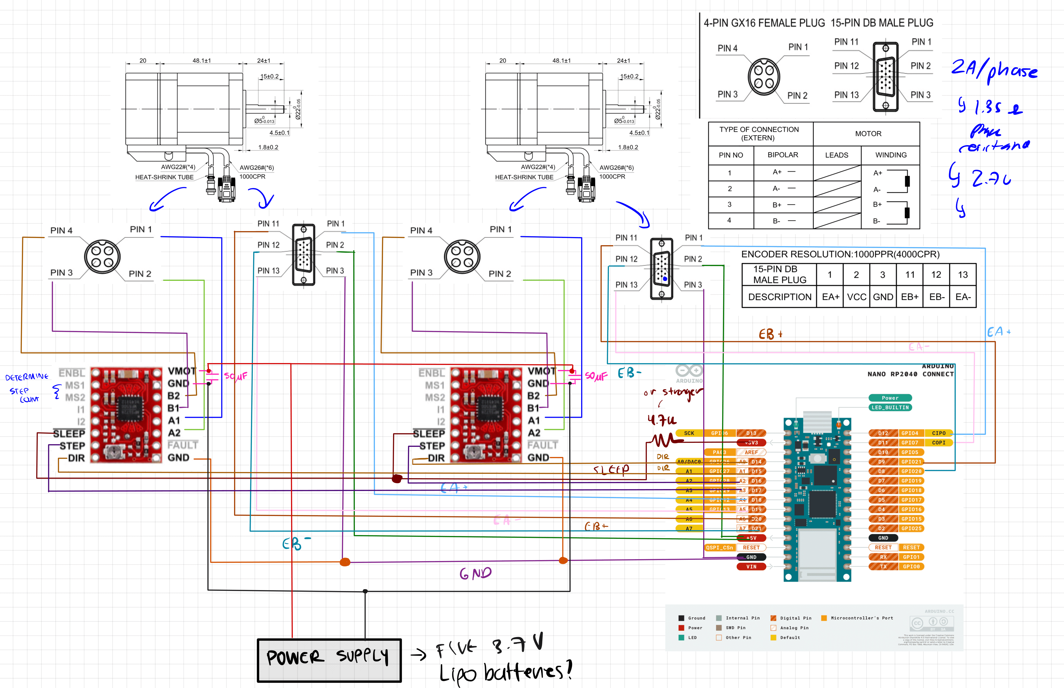
- Designing the circuit that would connect all of the components together, including using any recommended circuits provided by their datasheets and corresponding websites. My hand-drawn schematic is shown below.
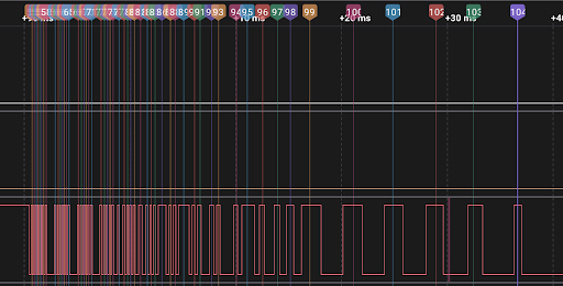
- Now came time to work on the code. I started from a very basic set of code and simply made my stepper motor take very slow steps and read the encoder output with the Digital Logic Analyzer.
Unfortunately, while I was able to develop the control code for the motors, I was unable to make it work because of the really erratic behavior of the encoders. With every step of the motor, the encoder would vibrate many times back and forth. No matter how many times I analyzed it, I could not determine a consistent pattern for the amount of times it would vibrate. And without a consistent pattern, I cannot properly control my motor because my code will not be able to accurately determine how many steps the motor actually took.
Here is a sneak peak photo of my DLA output analyses: