Project: Flight Data Recorder
Status: Archived project for the UBC AeroDesign Team (Sensors and Controls Subteam)
Quick Description
One of my previous projects was to design the Flight Data Recorder for our plane. This involved producing a set of requirements for the Black Box and choosing the optimal sensors for accurate data acquisition. I also had to scan datasheets for component restrictions, recommended circuits, and communication protocols.
Materials Used
- KiCad Software
- Teensy 3.6 microcontroller
- many other tiny electrical components
- Many, Many Websites
Helpful Links for Explorers
Step By Step Playthrough
For context, a Flight Data Recorder is used to collect all physical data during a flight (velocity, acceleration, roll/pitch/yaw, etc). This data can then be used to analyze any problems that may have occurred during the flight and used for troubleshooting.
This will not be a detailed walkthrough, but here are the general steps I used:
- Determine the main microcontroller that will be used to manage all of the sensor input data management (based on availability in design team stock)
- Select sensors that met the requirements we needed for our design team competition. These were the considerations: a) accuracy for data measurements b) allowable operating temperatures c) available type - SMD, THT, etc.
- Once the sensors are selected, you have to look through their datasheets to find the recommended circuits. These extra recommended components will help sort any noise produced by the sensor, and in general will optimize their performance.
- Design the PCB schematic using KiCad.
- Write the firmware for collecting the data continuously during flight. This is very easy as it just requires a simple loop where you read from every sensor (the flight data recorder just collects data, it does not do any sensor fusion).
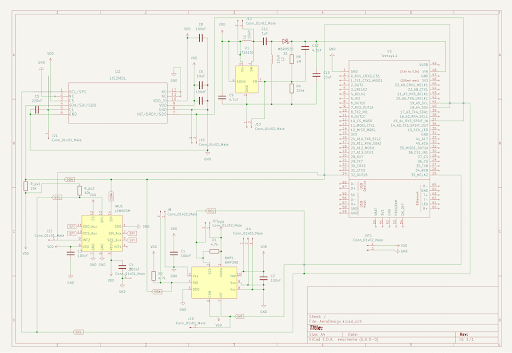
This is what the schematic looked like:
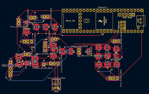
And this was the PCB layout (keep in mind this was my first time designing and optimizing a pcb layout XD):